We will place all reports on do-it-yourself activities and renovations here.
Mini picture frame from the 3D printer
Idea
For smaller pictures, photos, etc. you often need a matching picture frame to the photo, the drawing etc. As a 3D printer owner, it should make sense to use CAD software to design your own picture frame and then print it out on your 3D printer.
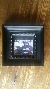
Furthermore, the CAD design process can be a good exercise for improving your CAD-Software-Skills. In our example, an already existing picture frame made of wood in the small rectangular format approx. 140 x 140mm is used as a template:
Design
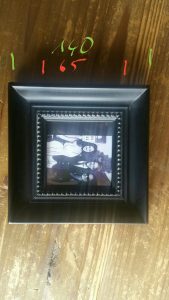
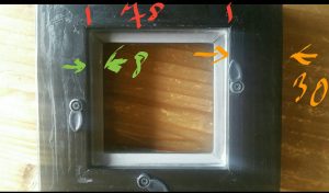
Based on the existing object, the corresponding photos of the object were first taken and provided with the dimensions relevant for the design:
The CAD software I use is Fusion 360. The software offers really a lot of possibilities, the ability to create construction drawings based on photos of existing objects is only one among plenty of very useful features.
Photos as a template for design drawing
To do this, you import the photos as 'Attached View Area' into the Fusion360 design. Subsequently, the imported images must be calibrated using the appropriate function, i.e. the drawing is adjusted based on a measurement on the photo. 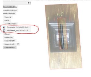
For the drawing I imported 2 images as front view and side view. After the import, the two images still have to be assigned to the respective coordinate space. Based on this, I did the corresponding construction drawing of the frame profile (cross-section of the frame element):
 The profile was initially set to 1mm in the drawing dialog of F360 in wall thickness using the offset function of F360 drawing functions. This means that the extrusion of the profile produces hollow bodies with the wall thickness set to 1mm.
Extrusion and positioning of the items
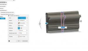
The extrusion of the profile was done as symmetrical extrusion with 30mm in each direction:
The straight piece of the frame thus created was copied in F360 by using copy & paste in the needed amount. Furthermore, two construction planes were created, which were used for the 45 ° division of the lines, ie a + 45 ° plane and a -45 ° plane. From this the corner pieces of the frame have been created:
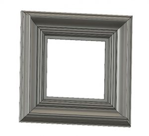
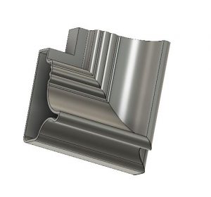 After the first straight piece and the first corner piece have been created, copies of the bodies could be made and then assembled by rotation and positioning to the appropriate positions of the completed frame of all individual bodies. By combining the single bodies, a new component was created that represents the already almost completed frame:
Backside of picture frame
As each hollow body was produced from the frame profile, a solution had to be created on the backside for taking the image object:
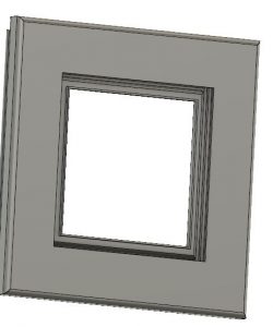 To remedy this problem, a separate body was constructed, which was then inserted into the resulting cavity:
Ornament of the window cutout
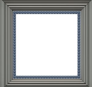
In the cut-out window on the front of the frame a circumferential ornament should be inserted for decoration. For this purpose, a semi-spherical element was first created and positioned on the crop window:
With the help of the Fusion360 - function 'Arrangement on Path' , bodies can be arranged on paths in any amount and any distance. A feature that proves to be very helpful here. Thus, from the one semi-spherical element, the corresponding amount of decorations could be arranged in a rectangular arrangement on the window cutout of the front side:
Back cover and frame stand with hinge
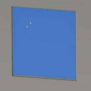
In order for the objects applied to the back to be fixed from the back, a lid had to be constructed for the back. Furthermore, a correspondingly dimensioned frame stand should be created, which could be attached as a folding display on a corresponding hinge to the back of the picture frame. The back was extruded as a rectangular surface with a thickness of 2mm as a separate body according to the dimensions of the back cutout. 2 small holes at a distance of 7 mm were taken into account to fix the stand:
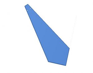
At the same plane the stand was drawn and also extruded as a separate body with a thickness of 2 mm:
For the attachment of the stand on the back I have opted for a hinged hinge, so that the stand can also be folded to save space on the frame. I have not constructed the hinge by myself but resorted to a thingiverse available part: https://www.thingiverse.com/thing:2187167
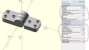
This hinge can be configured as desired using OpenSCAD according to a wide variety of criteria and then generated as an STL file. I specified the following parameters in OpenSCAD when generating the hinge:
A small hinge that can be attached to the stand and the frame back.
3D-Print of the picture frame
The printing of the frame in original size of about 157 x 157 mm should be easily possible on any standard 3D printer with the appropriate print bed dimensions. Strong attention shouldbe given to the adjustment of the support structures, due to the overhangs of the frame elements and hollow bodies a print without support structures isn't possible. For a first draft, I've set the density of the support structures to 5% and the fill pattern to Triangles. This also reduces the costs for the needed filament. As print resolution, I've chosen 0.3mm resolution (at 0.4 mm nozzle) for a draft. The other relevant print parameters can be found in the following picture of the Cura settings:
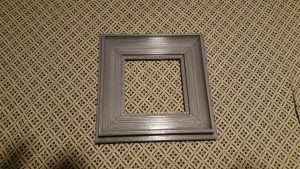
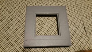
With these settings, the 3D-print on my anycubic i3 mega in PLA grey at 80mm / s printspeed took about 5 hours 45 minutes. I found the result quite impressive for a first rough draft:
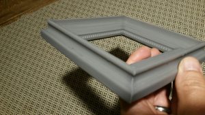
3D-Print of the other parts of the picture frame
The back and the frame stand can be printed very easily and quickly with standard settings due to the small thickness. Neither support structures nor Brim or Raft are necessary here. The print resolution does not have to be particularly high, I havehad good success with 0.3mm resolution printed at 80mm / s printspeed, both parts were printed after about 20 minutes. The small hinge should be printed in high Resolution so that it can be rotated after printing. I have made very good experiences with 0.1mm print resolution at a reduced print speed of 40mm / s. The lockplates can be printed together in the required quantity. Again, they should be printed with high resolution, since the parts are very small dimensioned. The printspeed should also be reduced accordingly. Again i have had good experience with 0.1mm print resolution and 40mm / s printspeed.
Assembly
The assembly of the printed parts can be done quickly. Place the hinge on the back cover in accordance with the pre-punched drill holes. I did not use screws here and used super glue instead. Attach the stand to the other end of the hinge (screw or glue):
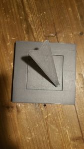
After the four cover plates are screwed on the back and the object is inserted into the frame, the finished picture frame presents itself in full beauty:
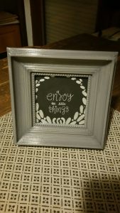
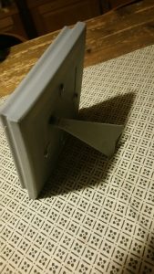
Download of the STL-Files for 3D-Print
All parts required for assembly for 3D printing (with the exception of the hinge which is available here) are freely available on thingiverse under the following link:
https://www.thingiverse.com/thing:3597522
Please note the license terms specified there. The freely available picture frame is provided with a lettering (my web address) on the backside . This lettering may not be removed or changed in accordance with the terms of the license.
If you are interested in an STL file without the lettering, this can be requested and purchased from me.
Spice jar for grenade-sharp things
Since more and more bags and packaging of various spices occured on our spice rack , I was looking for some beautiful and practical spice jars.
Requirements
3D- printable should be the most important feature of the object, so my first stop in Internet research was thingiverse.com once again. There I noticed an admittedly unusual design of a spice jar in the form of a hand grenade.
Design
For hot spicy things such as cayenne pepper and chilli this design seemed very suitable:
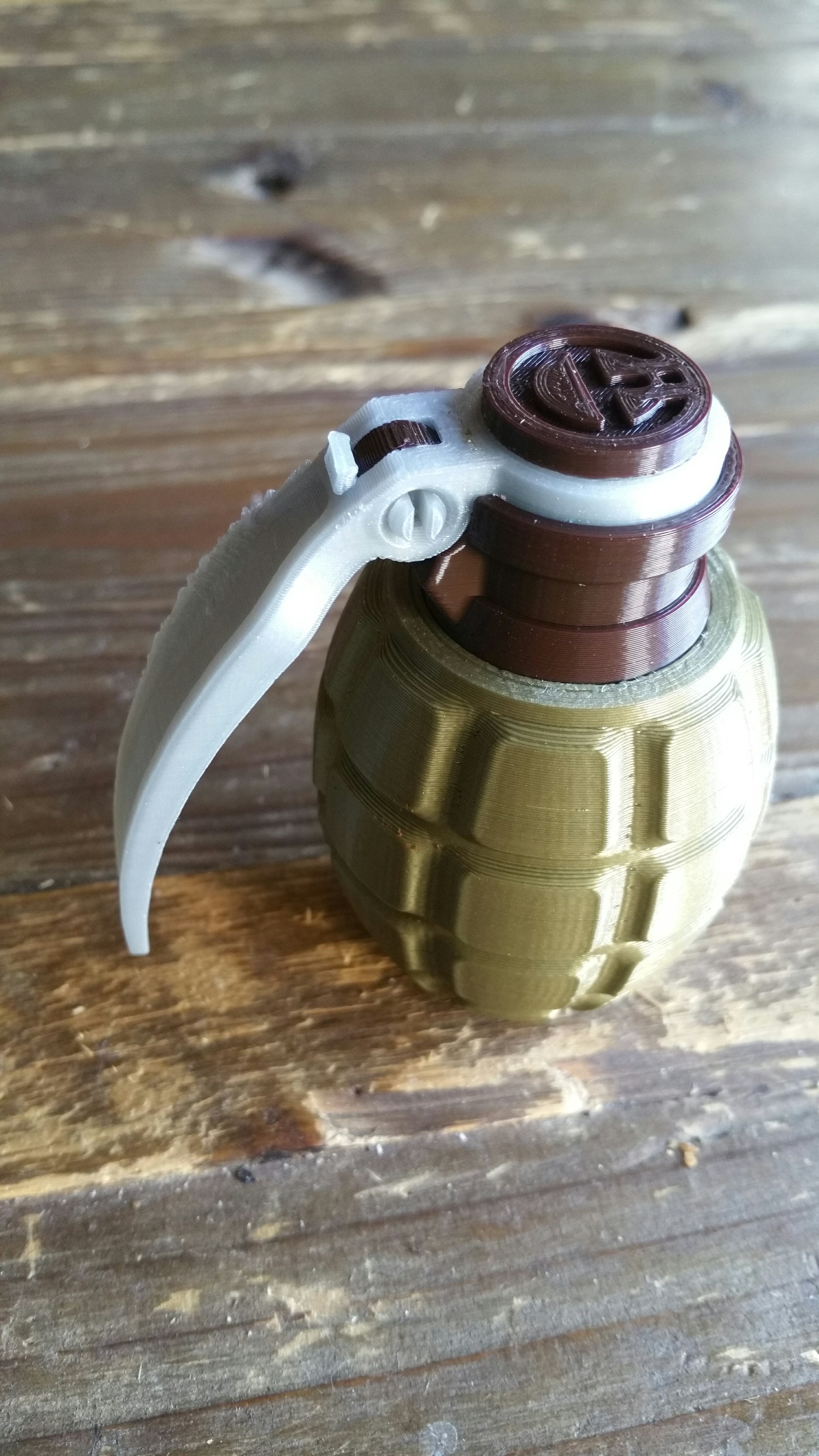 Design is available on thingiverse for Download
Details
The advantage of the design is that it can be printed in a very uncomplicated way. There are 6 different parts to print:
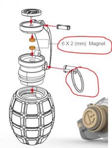 The red rimmed parts (metal ring and magnets) must be added separately. However, I have initially dispensed the magnets, to open and close the container on the lever works but not so elegant as it might with magnets.
3D-Print
Printing of the items was very uncomplicated. Support structures and largely Raft could be omitted. The material used was cheap PLA filament of owlsat (ebay) for only 16 € per kg.
All was printed on my anycubic i3 mega with a 210 degree nozzle temperature and a tape-backed printbed area. Thus, it was possible to print without heating of the printbed.
First, the lower shell was printed in green PLA:
Here it is important that you print bottom-up with the underside upwards. The object is positioned that way as default in the slicer. Otherwise it would have to be printed with support. I printed with 0.4mm nozzle and 0.25mm resolution, at rel. high printing speed of 80mm / s. Only the first layers were printed at reduced speed at 40mm / s.
Since all other parts should be printed differently in color, a filament change was required. Afterwards the printing countinued with the lever in PLA silver gray:
As shown, the lever could also be printed without support also with 0.4mm nozzle and 0.25mm resolution at 80mm / s print speed.
Same color the two small parts needed to be printed for mounting at the bigger parts. Therefore, these were sliced and printed in a common print job. Due to the small size here, they must be printed with a small Raft, for better printbed- adhesion.
 Last but not least, the lid and threaded attachment for the housing had to be printed. Both should be done in dark brown, so both objects were printed together in one print job.
The thread attachment is best printed in the correct position, ie positioned top upside . Then you can print without support, because the overhangs shouldn't be a problem.
Assembly
The assembly of the parts is very simple according to the exploded view shown on image in the head of this post. Prior to assembly, no further machining of the parts, such as grinding, sanding etc., should be required, the tolerances of the parts have been considered sufficiently large in the design. The threaded cover can be screwed into the housing easily and fits well. The (ornamental) lid on the threaded cover must be secured with a suitable adhesive.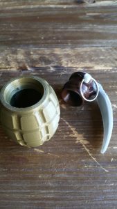
After assembly, the cover for filling the inside can be easily removed and screwed on again at any time. The spout opening can be easily opened and closed again without magnets via the lever.
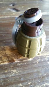 My 3D- print can be seen on thingiverse too as a make.
And the Oscar goes to...OPENSCAD !
Configurable Oscar statue for self-printing on 3D printer
Design idea
At the annual Oscar ceremony, these decorative Oscar trophies are presented. I wanted to create a statue based on this design, which should be configurable and of course also 3D-printable.
I wanted to give this object as a gift to a good friend, as a thank you that he has produced our wedding film so wonderful.
Realisation
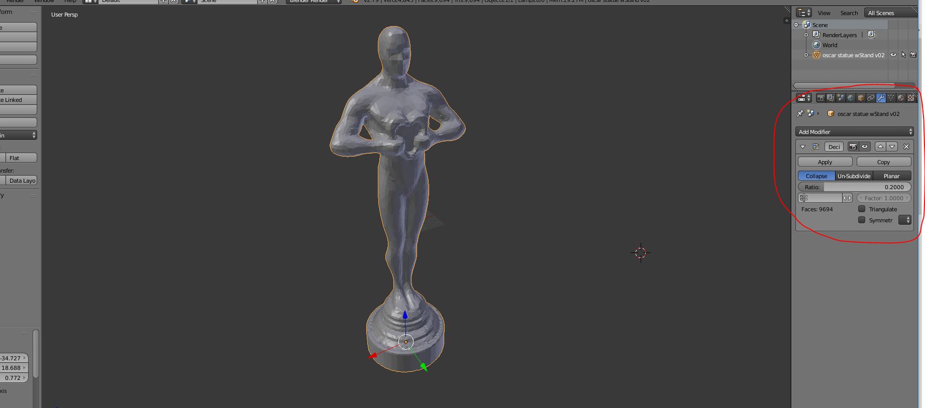
The original template of the Oscar statue is available in the Internet in various image formats. Starting from a good photo, I began to be creative with excellent help of Opensource 3D software Blender.
Blender is freely available as software and can be downloaded for free at blender.org. This gives you a lot of possibilities to get creative in 3D. However, the software is not "self-explanatory". Therefore, as a blender beginner it is recommended to get acquainted with the immense variety of functions of this tool. There are a lot of good tutorials and tutorials on the net here, youtube is a hot tip here, as there are some very good video tutorials on Blender available. But I did not only need the design as a blender model, but it also needed the Labeling of the socket should be configurable, yet another very useful CAD tool had to be included. The open-source tool OPENSCAD can be used to create geometric bodies using a programming language. The bodies can be parameterized at runtime via appropriate OPENSCAD customizers via appropriate program parameters or variables. OpenSCAD is also available as a free download via openscad.org.
In any case, I recommend that you download the latest version as a development snapshot, as the stable versions currently do not have the customizer functionality. Tutorials are again very abundant in the network. Especially recommended for beginners are the tutorials available on the OpenSCAD homepage.
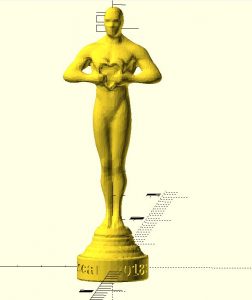
Last but not least the Blender model had to find its way into the OpenSCAD environment. By default, Blender does not offer the option to export models in OpenSCAD format. However, a corresponding add-on is available via github. After the download and successful installation of the add-on in Blender you have the option in the export menu of Blender to select the format openscad. Thus the generated file can be opened in OpenSCAD. In OpenSCAD, the model structure is available as a polyhedron body. The net- structure of the model is stored via corresponding coordinates in the form of a multimatrix. In order to provide the socket with configurable writings, the program code generated from Blender has been correspondingly supplemented in OpenSCAD and provided with parameters for the OpenSCAD customizer:
As a parameter, besides the text line, I have made available also other parameters such as font and font size. This allows the socket to be largely labeled or configured as desired. In OpenSCAD, the program code can also be adapted by the user at will to his own interests, so there is still room for further changes and improvements.
Once the parameters have been set via the customizer, an STL file can be generated from OpenSCAD for 3D printing. However, due to the complexity of the multimatrix of the Oscar model, the rendering takes a little longer, depending on the performance of the computer being used. On my DELL G3 laptop with Core i7 8.Gen. CPU and GTX1060 graphics card as well as 32GB RAM it's relatively fast, after about 10 seconds the rendering is finished.
Since OpenSCAD is also the basis for the customizer provided by thingiverse ONLINE, the model available on thingiverse can also be configured directly online on thingiverse.com. However, I only use OpenSCAD locally on the PC for the corresponding OpenSCAD models, because the thingiverse customizer online in my browser is unfortunately not reasonably usable.
3D-Print
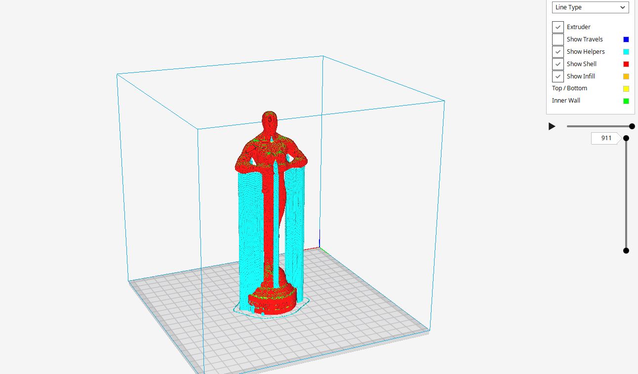
The 3D printing of the STL file generated from OpenSCAD was then prepared using the slicer software CURA. In Cura I have set the layer thickness to 0.2mm, 10% Infill is absolutely sufficient. I added a PAUSE-AT-HEIGHT extension to change the color of the filament after printing the base. I also had to print support because the overhangs on the model's arms were too big:
Overall, the print on my anycubic i3 mega 3D printer took just under 4 hours.
The result is published as make on thingiverse.com
The openSCAD-Object is available as download on thingiverse:
3D printing: KitchenAid adapter for soda stream
3D-Print: KitchenAid Adapter for Sodastream
Our KitchenAid Sodastream looks very chic, so beautiful in black / silver:
After some Problems at the beginning it works very well now. Bubbles our excellent Bühlertäler tap water. However, it has a small flaw: there is no suitable glass bottle for this model.
Neither Sodastream nor the Kitchenaid manufacturer provide suitable products for this purpose. That's a pity, so it was obvious to see if there is a suitable adapter with which smaller standard glass bottles with standard threaded fasteners can be docked to the kitchenaid connection.
First I tried the following part:available on thingiverse:
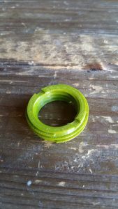
That was also very straightforward and easy to print. After testing i found out, only for sodastream with screw thread suitable, so not for our KitchenAid sodastream.
Next thing i tried was this:

Also not suitable for our kitchenaid, because the lower edge was missing for the gripping arm.
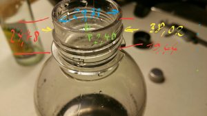
Unfortunately so, nothing suitable for our device was available on thingiverse.com as stockpart. That's why I took the appropriate measurements, first from the Kitchenaid / Sodastream bottleneck:
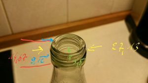
then from the bottleneck of a smaller lemonade glass bottle:
With these measurements, I was able to use the CAD software fusion360 to construct a suitable adapter that makes the glass bottle fit the Kitchenaid connection. The result is prepared for 3D printing as an STL file available here on thingiverse.com for download .
As printing material i recommend a material as stable as possible such as ABS or similar to give the adapter the necessary strength and stability. Support material or brims / rafts for print-to-bed adhesion are not required for printing. The print resolution should not be set too low due to the modeled thread, I have made good experiences with 0.15mm at 0.3mm nozzle size.
IMPORTANT !!
Please be careful when using the adapter. The Sodastream is a pressure device, and applying rapid pressure to a device not meant for such things can cause explosions and severe injury !!
I may not be held responsible for any damage or injury that may occur when using the adapter. Use at your own risk !
Lotus blossom from the 3D printer
This beautiful lotus blossom was 3D-printed with very favorable PLA filament in interesting green camouflage shade:

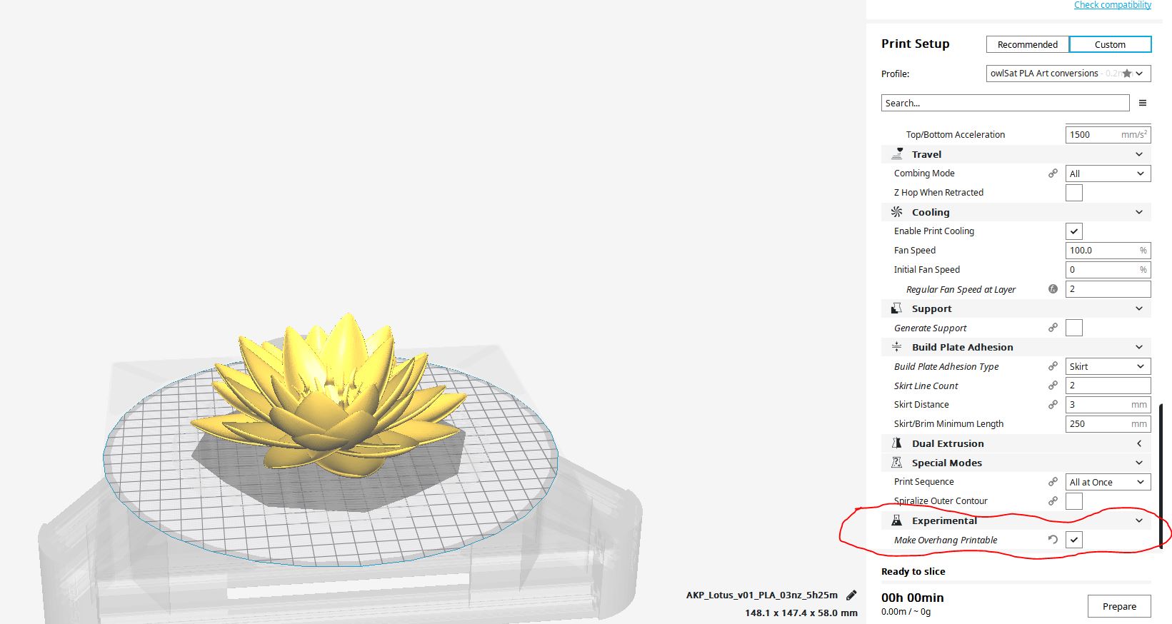
To avoid support I used the Cura option - Make Overhang Printable -
This makes it easy to print the object without support, brim / raft, etc. on my anycubic delta Kossel plus 3D printer. The result can be found as a make on thingiverse.com:
https://www.thingiverse.com/thing:640755








Comments